In solar power plant earthing, important elements are taken into account.
Steps for earthing a solar plant:
Proper earthing of a solar power plant is crucial to ensure electrical safety and system performance. Here are the general steps involved in the process of earthing a solar plant:
Design and planning: Before starting the installation, ensure that the solar plant's earthing system is appropriately designed. The design should comply with local electrical codes, regulations, and industry standards. Consider factors such as soil resistivity, fault current, and the number of grounding electrodes required.
Site preparation: Prepare the site by clearing any vegetation or obstacles around the area where the earthing system will be installed. Make sure the area is free from any underground utilities or obstructions.
Grounding electrodes: Determine the type and number of grounding electrodes needed based on the system design and requirements. Common grounding electrodes used in solar plants include copper-clad or galvanized steel rods, conductive concrete, or ground loops. The grounding electrodes should be of sufficient length and properly spaced to achieve the desired resistance to earth.
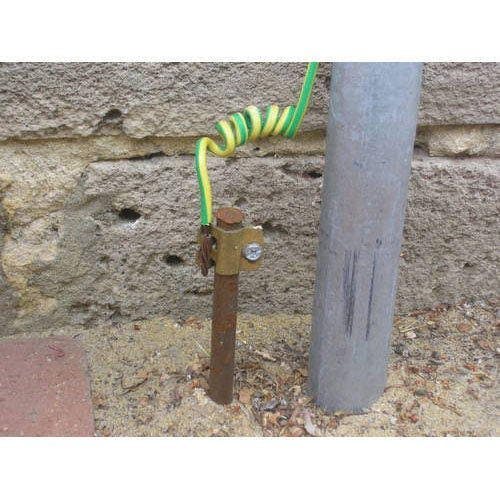
Electrode installation: Install the grounding electrodes according to the design specifications. This typically involves driving the rods into the ground using appropriate tools and equipment. Ensure that the electrodes are firmly in place and adequately buried to provide good electrical contact with the surrounding soil.
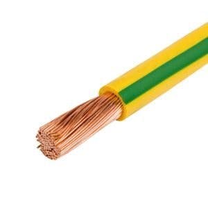
Interconnection: Connect the grounding electrodes together using suitable conductors, such as copper or aluminum wires, in accordance with the design. Properly terminate and securely connect the conductors to the electrodes to ensure low-resistance connections.
Bonding: Establish bonding connections between the solar panels, metal frames or racking, inverters, and other metallic components of the solar plant. This helps to create equipotential bonding and prevents potential differences that could pose electrical hazards. Use appropriate bonding conductors or straps made of copper or other suitable materials.
Grounding conductor: Install a grounding conductor that connects the grounding electrodes and the bonding system. This conductor carries the fault current safely to the earth in the event of an electrical fault. The size of the grounding conductor should be determined based on the fault current calculations and the requirements of local codes and standards.
Testing and verification: Once the earthing system is installed, perform electrical tests to verify the system's effectiveness and ensure that the resistance to earth meets the required standards. Common tests include soil resistivity measurements, ground resistance testing, and continuity checks.
Documentation and maintenance: Keep thorough documentation of the earthing system installation, including diagrams, test reports, and maintenance records. Regularly inspect and maintain the grounding system to ensure its continued effectiveness and safety.

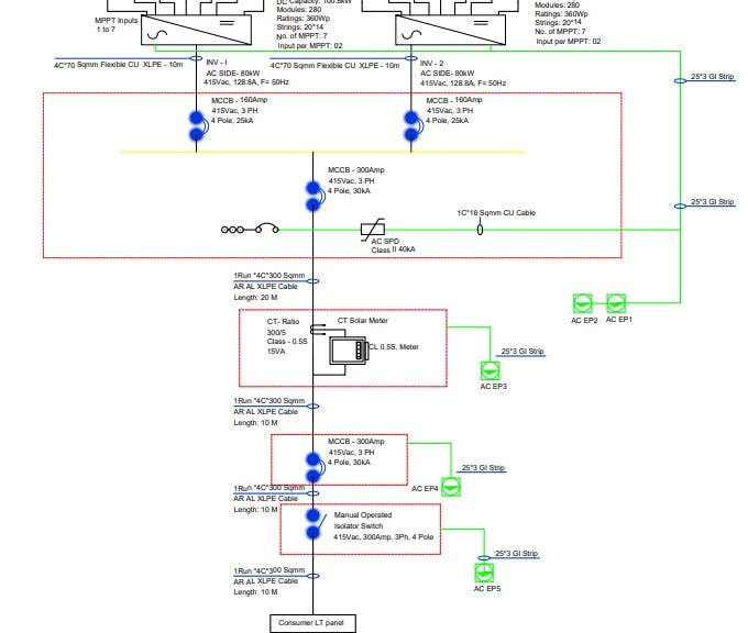
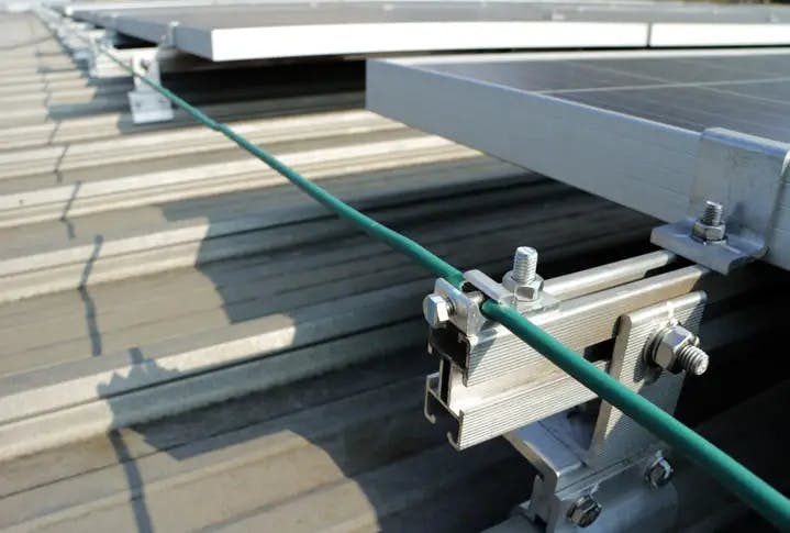
Fig. 1: Earthing in Solar Power Plant
How to calculate the number of earthing pit in solar plant earthing:
Calculating the number of earthing pits required for a solar plant earthing system involves considering factors such as the size of the plant, soil resistivity, fault current, and applicable electrical codes and standards. Here's a general approach to estimating the number of earthing pits:
Determine the maximum allowable earth resistance: Consult local electrical codes or standards to determine the maximum permissible earth resistance for the solar plant. This value typically varies depending on the application and region but is usually in the range of 1-10 ohms.
Measure soil resistivity: Conduct a soil resistivity test at the site where the solar plant will be installed. This test helps determine the resistivity of the soil, which affects the grounding system's effectiveness. Soil resistivity is measured in ohm-meters (Ω.m).
Calculate the required electrode resistance: Using the maximum allowable earth resistance and the soil resistivity, calculate the desired resistance for each grounding electrode. The formula used is:
Required electrode resistance (ohms) = Maximum allowable earth resistance (ohms) / (Number of electrodes x Soil resistivity (ohm-m))
Select grounding electrode type and size: Choose the type and size of grounding electrodes based on factors such as soil conditions, regional requirements, and design specifications. Common grounding electrode options include copper-clad or galvanized steel rods, conductive concrete, or ground loops.
Calculate the number of earthing pits: Divide the total calculated required electrode resistance by the resistance provided by each grounding electrode. This will give you the approximate number of earthing pits needed to achieve the desired overall resistance.
Number of earthing pits = Total calculated required electrode resistance / Resistance provided by each grounding electrode
Consider redundancy and safety factors: It's recommended to have redundant earthing pits to ensure system reliability and safety. The exact redundancy factor may depend on specific project requirements, electrical codes, and industry best practices.
Adjust for site-specific conditions: Evaluate any site-specific conditions that may influence the number and layout of earthing pits. This includes factors such as ground surface area, physical obstructions, and proximity to other structures or utilities.
How to calculate the earthing cable size:
Calculating the earthing cable size involves considering factors such as the maximum fault current, the duration of the fault, and the acceptable voltage drop. Here's a general approach to estimating the appropriate earthing cable size:
Determine the maximum fault current: Consult electrical system design or relevant standards to determine the maximum fault current that the earthing system will need to handle. This value is typically provided in kiloamperes (kA).
Select the fault duration: Determine the duration of the fault that the earthing cable should be able to withstand. This value is usually specified by electrical standards and can range from a few milliseconds to several seconds.
Determine the acceptable voltage drop: Decide on the acceptable voltage drop in the earthing cable during a fault condition. Electrical standards often specify the maximum allowable voltage drop as a percentage of the system voltage.
Calculate the cross-sectional area: Using the determined fault current, fault duration, and acceptable voltage drop, calculate the cross-sectional area of the earthing cable required. This calculation can be done based on Ohm's Law:
Cross-sectional area (mm²) = (Fault current (kA) x Fault duration (s)) / (Voltage drop (V) x Specific resistance of the cable material (Ω.mm²/m))
Select the cable size: Based on the calculated cross-sectional area, choose the nearest standard cable size that meets or exceeds the calculated value. Cable size tables provided by manufacturers or electrical standards can be used for reference.
Consider other factors: Take into account practical considerations such as the availability of the selected cable size, installation requirements, and environmental factors (e.g., ambient temperature) that may influence cable performance.
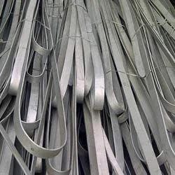
How to select the GI flat for earthing:
When selecting a GI (galvanized iron) flat for earthing, several factors need to be considered to ensure proper conductivity and effective grounding. Here's a general approach to selecting a GI flat for earthing:
Determine the required cross-sectional area: The cross-sectional area of the GI flat is an essential consideration as it directly affects its conductivity. The required cross-sectional area is typically determined based on the maximum fault current, which should be able to safely dissipate into the earth.
Calculate the cross-sectional area: Calculate the cross-sectional area of the GI flat based on the maximum fault current using the following formula:
Cross-sectional area (mm²) = Fault current (A) / Specific conductivity of GI (Ω.mm²/m)
The specific conductivity of GI can be obtained from technical data or standards.
Choose the appropriate size: Once the required cross-sectional area is determined, select a GI flat size that meets or exceeds the calculated value. GI flats are available in various sizes and thicknesses, typically specified in millimeters (mm).
Consider practical factors: Consider practical factors such as the availability of the selected GI flat size, installation requirements, and local regulations. It's important to ensure that the GI flat is compatible with the earthing system design and can be easily connected to other components of the grounding system.
Quality and durability: Ensure that the GI flat meets the necessary quality and durability standards. Look for GI flats that are properly galvanized to resist corrosion, as they will be in direct contact with the soil.
Installation: Follow proper installation guidelines and ensure that the GI flat is securely and effectively connected to the grounding system. Proper connections, such as using suitable connectors or clamps, should be made to establish a low-resistance path to the ground.
How to calculate the earthing Pit resistance:
To calculate the earthing pit resistance, you can use a method known as the "fall of potential" or "three-point" measurement. Here's a step-by-step approach:
Disconnect the earth electrode: Ensure that the earthing system is temporarily isolated from the electrical system by disconnecting the earth electrode you want to measure.
Set up the test equipment: Use a digital earth tester or a ground resistance tester, which typically consists of a voltage source and current measurement capability. Connect the test leads of the instrument as follows:
Connect the "P1" or "Current" terminal to the ground electrode or earth pit under test.
Connect the "P2" or "Potential" terminal to a known reference electrode, which is typically a separate electrode positioned far away from the earth pit under test.
Connect the "C" or "Current" terminal to a current spike or probe, which is inserted into the ground between the test electrodes.
Measurement process: Start the measurement process by following these steps:
a. Apply a known current to the ground electrode under test using the tester.
b. Measure the voltage drop between the earth electrode under test and the reference electrode using the potential terminal of the tester.
c. Record the current value and voltage drop value indicated by the tester.
Calculation: With the measured current and voltage drop values, calculate the earth pit resistance using Ohm's Law:
Earthing pit resistance (Ohms) = Voltage drop (Volts) / Current (Amperes)
Multiple measurements: To improve accuracy, perform multiple measurements at different positions around the earth pit, especially if it is a large grounding system. Calculate the average resistance from these measurements.
It's important to note that soil resistivity plays a significant role in the overall earthing system performance. The calculated resistance of the earthing pit should be compared with the acceptable values specified by local electrical codes, regulations, or engineering standards.
How to calculate the earthing strip resistance:
To calculate the resistance of an earthing strip, you can use the "resistivity method" or the "parallel resistor method." Here's a step-by-step approach using the resistivity method:
Determine the dimensions: Measure the length, width, and thickness of the earthing strip. These measurements are typically in meters (m).
Measure the resistivity of the soil: Perform a soil resistivity test at the location where the earthing strip will be installed. The resistivity of the soil is measured in ohm-meters (Ω.m).
Calculate the effective resistivity: Determine the effective resistivity of the soil based on the measurement results and the installation depth of the earthing strip. This can be done using empirical formulas or soil resistivity models provided by electrical standards or engineering resources.
Calculate the resistance: With the dimensions of the earthing strip and the effective resistivity of the soil, calculate the resistance using the following formula:
Resistance (Ohms) = (Resistivity (Ω.m) x Length (m)) / (Width (m) x Thickness (m))
Consider multiple strips: If multiple earthing strips are installed, calculate the resistance for each strip using the same formula. Then, combine the resistances using the parallel resistor formula:
Total Resistance (Ohms) = 1 / (1/R1 + 1/R2 + 1/R3 + ... + 1/Rn)
Where R1, R2, R3, ... Rn are the resistances of individual earthing strips.
It's important to note that the resistivity of the soil can vary with depth, moisture content, and other factors. Therefore, it's recommended to conduct soil resistivity tests at different depths and consider the worst-case scenario or average resistivity value for accurate calculations.
Difference between DC side earthing and AC Side earthing in Solar Power Plant:
In a solar power plant, the main difference between DC side earthing and AC side earthing lies in the electrical characteristics and components involved. Here are the key distinctions:
DC side earthing:
Voltage level: The DC side of a solar power plant deals with the direct current generated by the solar panels. It typically operates at lower voltages, such as 12V, 24V, or 48V, depending on the configuration of the system.
Components: On the DC side, the primary components include solar panels, DC combiner boxes, DC cables, and DC isolators.
Earthing purpose: DC side earthing is primarily done to ensure the safety of personnel and equipment in case of fault conditions, such as a short circuit or ground fault. It provides a path for the fault current to flow safely to the ground, minimizing the risk of electrical hazards.
Earthing system: DC side earthing typically involves grounding the negative terminal of the solar panels and other DC equipment. The negative terminal is usually connected to the earthing system, which may consist of grounding electrodes, conductors, and a grounding bus.
AC side earthing:
Voltage level: The AC side of a solar power plant deals with the alternating current generated by the inverters. It operates at higher voltages, such as 230V, 400V, or even higher, depending on the system design and grid connection requirements.
Components: On the AC side, the main components include inverters, AC combiner boxes, AC cables, and AC circuit breakers.
Earthing purpose: AC side earthing is also done for personnel and equipment safety. It ensures that any fault currents or leakage currents in the AC system are safely redirected to the ground, preventing electrical hazards.
Earthing system: AC side earthing typically involves grounding the neutral conductor of the AC system. The neutral point of the transformer or inverter is connected to the earthing system, which may include grounding electrodes, conductors, and a grounding bus.

Earthing on Solar Mounting Structure:
Earthing on solar mounting structures is an important aspect of ensuring the safety and performance of a solar power system. Here are some key points to consider regarding earthing for solar mounting structures:
Purpose of earthing: The primary purpose of earthing on solar mounting structures is to provide a path for fault or leakage currents to safely dissipate into the ground. This helps protect personnel and equipment from electric shocks and reduces the risk of fire or damage to the system.
Bonding and equipotentiality: Solar mounting structures, including racking and frames, should be properly bonded and connected to the overall earthing system of the solar installation. This creates equipotential bonding, ensuring that all metal components of the system are at the same electrical potential, minimizing the potential for voltage differences and electrical hazards.
Grounding electrodes: Grounding electrodes, such as grounding rods or plates, are typically installed at specific locations around the solar array. These electrodes provide a low-resistance path to the ground for fault or leakage currents.
Bonding conductors: Suitable bonding conductors, such as copper or aluminum wires or straps, should be used to connect the solar mounting structure to the grounding electrodes. These conductors should have sufficient size to handle fault currents and ensure low-resistance connections.
Grounding lug: Solar mounting structures often have dedicated grounding lugs or bonding points where the bonding conductors can be securely connected. These lugs should be designed to accommodate the required conductor size and provide a reliable connection.
Installation considerations: During the installation process, care should be taken to ensure that the mounting structure components are properly bonded and interconnected. This includes using appropriate hardware, connectors, and techniques to establish reliable electrical connections.
Compliance with codes and standards: It is essential to follow local electrical codes, regulations, and standards when designing and implementing the earthing system for solar mounting structures. These codes may specify the required size of bonding conductors, resistance limits, and other requirements to ensure safety and compliance.
Regular maintenance and inspection: Regular maintenance and inspection of the earthing system are important to verify its effectiveness and identify any potential issues or deterioration over time. This includes checking for proper bonding, corrosion resistance, and continuity of the grounding conductors.
Earthing on solar DC combiner box:
Earthing on solar DC combiner boxes is an essential aspect of electrical safety and system performance. Here are some key points to consider regarding earthing for DC combiner boxes in a solar power system:
Purpose of earthing: The primary purpose of earthing the DC combiner box is to provide a safe path for fault currents to flow into the ground in the event of a fault or leakage in the DC circuit. This helps protect personnel and equipment from electric shocks and reduces the risk of fire or damage to the system.
Grounding the metal enclosure: The metal enclosure of the DC combiner box should be properly earthed to prevent the accumulation of static charges and to provide a low-resistance path for fault currents. This ensures that any potential voltage difference or fault current can be safely discharged to the ground.
Grounding electrode: A grounding electrode, such as a grounding rod or plate, should be installed near the DC combiner box to establish a reliable ground connection. The grounding electrode provides a low-resistance path to the ground for fault or leakage currents.
Bonding conductors: Suitable bonding conductors, such as copper or aluminum wires or straps, should be used to connect the metal enclosure of the DC combiner box to the grounding electrode. These conductors should have sufficient size to handle fault currents and ensure low-resistance connections.
Grounding lug or terminal: The DC combiner box should have a dedicated grounding lug or terminal where the bonding conductor can be securely connected. This lug or terminal should be designed to accommodate the required conductor size and provide a reliable and permanent connection.
Compliance with codes and standards: It is crucial to adhere to local electrical codes, regulations, and standards when designing and implementing the earthing system for the DC combiner box. These codes may specify requirements such as the size of bonding conductors, resistance limits, and other specifications to ensure safety and compliance.
Regular maintenance and inspection: Regular maintenance and inspection of the earthing system for the DC combiner box are important to verify its effectiveness and identify any potential issues or deterioration over time. This includes checking for proper bonding, corrosion resistance, and continuity of the grounding conductors.
How to do earthing for Solar Central inverter in solar power plant:
When earthing a solar central inverter in a solar power plant, it is important to follow proper guidelines and electrical codes to ensure safety and compliance. Here's a general approach to earthing a solar central inverter:
Consult the manufacturer's guidelines: Review the manufacturer's documentation and guidelines for the specific solar central inverter being used. The manufacturer's guidelines will provide detailed instructions on the recommended earthing practices for their equipment.
Understand local electrical codes and regulations: Familiarize yourself with the local electrical codes, regulations, and standards applicable to solar power plants. These codes will outline the requirements for earthing and grounding systems.
Identify the grounding requirements: Determine the grounding requirements specified by the manufacturer and local codes. This includes understanding the number and type of grounding points required for the central inverter.
Grounding electrode system design: Design the grounding electrode system for the solar power plant, which includes determining the appropriate number and placement of grounding electrodes such as grounding rods or plates. Consult with a qualified electrical engineer to ensure the design meets the specific requirements of the installation site.
Bonding and equipotential bonding: Establish proper bonding connections between the central inverter, mounting structures, metal frames, and other metallic components in the solar power plant. This helps create equipotential bonding and minimizes voltage differences between different components.
Select the grounding conductor: Choose a suitable grounding conductor based on the manufacturer's recommendations and local codes. The conductor should be of appropriate size, material (such as copper or aluminum), and insulation rating to handle the expected fault currents.
Connect the grounding conductor: Connect the grounding conductor from the central inverter's grounding point to the grounding electrode system. Ensure proper termination and secure connections to establish a low-resistance path for fault currents.
Continuity checks and testing: Perform continuity checks and testing of the grounding system to ensure its effectiveness and compliance with electrical codes. This may include resistance measurements, insulation tests, and verifying proper bonding throughout the system.
Documentation and maintenance: Maintain thorough documentation of the earthing system, including diagrams, test reports, and maintenance records. Regularly inspect and maintain the earthing system to ensure its continued effectiveness and safety.
How to do earthing for ACDB in solar power plant:
Earthing for an ACDB (Alternating Current Distribution Box) in a solar power plant is essential to ensure safety and proper functioning of the electrical system. Here's a general approach to earthing an ACDB in a solar power plant:
Consult manufacturer's guidelines: Review the manufacturer's documentation and guidelines specific to the ACDB being used. The manufacturer's guidelines will provide instructions on the recommended earthing practices for their equipment.
Understand local electrical codes and regulations: Familiarize yourself with the local electrical codes, regulations, and standards applicable to solar power plants. These codes will outline the requirements for earthing and grounding systems.
Identify the grounding requirements: Determine the grounding requirements specified by the manufacturer and local codes for the ACDB. This includes understanding the number and type of grounding points required for the ACDB.
Grounding electrode system design: Design the grounding electrode system for the solar power plant, which includes determining the appropriate number and placement of grounding electrodes such as grounding rods or plates. Consult with a qualified electrical engineer to ensure the design meets the specific requirements of the installation site.
Bonding and equipotential bonding: Establish proper bonding connections between the ACDB, mounting structures, metal frames, and other metallic components in the solar power plant. This helps create equipotential bonding and minimizes voltage differences between different components.
Select the grounding conductor: Choose a suitable grounding conductor based on the manufacturer's recommendations and local codes. The conductor should be of appropriate size, material (such as copper or aluminum), and insulation rating to handle the expected fault currents.
Connect the grounding conductor: Connect the grounding conductor from the ACDB's grounding point to the grounding electrode system. Ensure proper termination and secure connections to establish a low-resistance path for fault currents.
Continuity checks and testing: Perform continuity checks and testing of the grounding system to ensure its effectiveness and compliance with electrical codes. This may include resistance measurements, insulation tests, and verifying proper bonding throughout the system.
Documentation and maintenance: Maintain thorough documentation of the earthing system, including diagrams, test reports, and maintenance records. Regularly inspect and maintain the earthing system to ensure its continued effectiveness and safety.
Earthing considerations for transformer:
Earthing considerations for a transformer are crucial to ensure the safety and proper operation of the electrical system. Here are some key points to consider for transformer earthing:
Transformer grounding: The transformer should be effectively grounded to provide a low-resistance path for fault currents and ensure the safety of personnel and equipment. The grounding method may depend on the type of transformer (e.g., power transformer, distribution transformer) and the specific installation requirements.
Neutral grounding: Transformers with a neutral point should have the neutral grounded. The type of grounding depends on the system configuration and requirements, and it can be solidly grounded, resistance grounded, or reactance grounded. The neutral grounding method is determined based on the system's fault current requirements, system grounding philosophy, and specific electrical codes and regulations.
Grounding of metal components: Metal components of the transformer, such as the tank and enclosure, should be effectively grounded to prevent the accumulation of static charges and to provide a safe discharge path for fault currents. Bonding conductors should be used to establish proper connections between metal components and the grounding system.
Grounding electrode system: A grounding electrode system, typically consisting of grounding rods, plates, or other electrodes, should be designed and installed to ensure proper grounding of the transformer. The design should consider factors such as soil resistivity, fault current magnitude, and local electrical codes and regulations.
Equipment bonding: Proper bonding of metal components, such as cable trays, conduits, and enclosures, to the transformer should be implemented to establish equipotential bonding and minimize voltage differences. Bonding conductors should be appropriately sized and installed to ensure low-resistance connections.
Lightning protection: Depending on the specific installation and site conditions, additional measures may be required for lightning protection. This may include the installation of lightning arresters, surge protection devices, or other lightning mitigation techniques to protect the transformer from lightning-induced surges.
Compliance with codes and regulations: It is essential to comply with local electrical codes, regulations, and standards when designing and implementing the earthing system for the transformer. These codes may specify requirements for grounding, bonding, electrode sizing, and other specifications to ensure safety and compliance.
Regular maintenance and testing: Regular maintenance and testing of the grounding system should be performed to ensure its continued effectiveness. This includes conducting periodic resistance tests, inspection of connections, and verification of proper bonding throughout the system.
Earthing in control and relay panel:
Earthing in a control and relay panel is a crucial aspect of electrical safety and proper functioning of the equipment. The primary purpose of earthing in a control and relay panel is to provide a safe path for the dissipation of fault currents and to maintain electrical equipment at a reference potential.
Here are some key points regarding earthing in a control and relay panel:
Equipment Earthing: All metallic parts of the control and relay panel, including the metal enclosure, frames, cable trays, and support structures, should be effectively earthed. This ensures that any leakage or fault currents are safely directed to the earth, minimizing the risk of electric shock to personnel and preventing damage to equipment.
Neutral Earthing: The neutral point of the power system, typically the star point of a transformer or generator, should be properly earthed. This is done to maintain the system voltage at a reference level and to facilitate the safe operation of protective relays. The neutral earthing may be achieved through a neutral earthing resistor (NER) or a solidly grounded neutral, depending on the system requirements.
Signal Grounding: In control and relay panels, there are often sensitive electronic devices, communication interfaces, and signal circuits. Proper grounding of these components is essential to prevent noise, interference, and voltage fluctuations. Signal grounding should be separate from the equipment grounding, and care should be taken to avoid ground loops that can cause unwanted currents or malfunctions.
Earth Electrode System: The control and relay panel should be connected to an earth electrode system, which consists of one or more earth electrodes such as copper rods or plates driven into the ground. These electrodes provide a low-resistance path for fault currents to flow into the earth. The earthing system should be designed and installed according to applicable standards and regulations to ensure effective fault current dissipation.
How to do earthing in Lightening arrester:
Proper earthing of lightning arresters is crucial for effective protection against lightning strikes and electrical surges. Here are the general steps to follow when earthing a lightning arrester:
Determine the Location: Choose a suitable location for the lightning arrester and its associated grounding system. It should be close to the equipment or structure being protected and ensure a short and direct path for the lightning current to reach the earth.
Earth Electrode System: Install an earth electrode system consisting of copper rods, plates, or conductive grids. The number and size of the electrodes depend on factors such as soil resistivity and the level of protection required. It is advisable to consult with a qualified engineer to determine the appropriate design for the earth electrode system.
Burial Depth: Ensure that the earth electrodes are buried at a sufficient depth to provide a stable and low-resistance connection with the surrounding soil. The depth may vary depending on local regulations and soil conditions. Generally, a depth of at least 1.5 to 2 meters is recommended for effective grounding.
Arrester Earth Terminal: Connect the arrester earth terminal to the earth electrode system using copper conductors or earthing cables. The conductor size should be selected based on the anticipated lightning current and local regulations. It is important to ensure low-resistance connections between the lightning arrester and the earth electrode system.
Bonding: Properly bond all metallic components associated with the lightning arrester, such as conductors, enclosures, and structural supports. Bonding ensures a continuous and low-impedance path for the lightning current and helps prevent potential differences that may arise during a lightning event.
Verification: Once the earthing system is installed, it should be tested to ensure its effectiveness. Conduct resistance measurements using specialized equipment to verify that the resistance between the arrester earth terminal and the earth electrode system is within acceptable limits.
Earthing in electrical switch yard:
Earthing in an electrical switchyard is a critical aspect of ensuring electrical safety, protecting equipment, and providing a reliable path for fault currents. Here are the general steps involved in earthing an electrical switchyard:
Design the Earthing System: Consult with a qualified electrical engineer or follow relevant standards and regulations to design the earthing system for the switchyard. Consider factors such as soil resistivity, fault current levels, and the specific requirements of the switchyard equipment.
Earth Electrodes: Install an appropriate number of earth electrodes based on the switchyard's size, soil resistivity, and expected fault currents. Common types of earth electrodes include copper rods, plates, or conductive grids. The electrodes should be strategically placed to ensure effective grounding.
Burial Depth: Dig pits or trenches at each earth electrode location and bury the electrodes at a suitable depth. The depth may vary depending on factors such as soil resistivity and local regulations. Generally, a depth of 1.5 to 2 meters is recommended to achieve good electrical contact with the earth.
Interconnection: Connect all the earth electrodes using copper conductors or earthing cables. The size of the conductors should be determined based on the anticipated fault current and local regulations. Ensure that the connections are mechanically strong and securely clamped or welded to minimize resistance.
Equipment Grounding: Ensure that all metallic equipment in the switchyard, including transformers, circuit breakers, switchgear, and control panels, are effectively grounded. Connect these equipment to the earthing system using dedicated grounding conductors. This helps to maintain equipment at a safe potential and facilitates the proper operation of protective devices.
Bonding: Establish bonding connections between metallic structures, equipment, and conductive parts within the switchyard. This helps to equalize potential differences, reduce hazards from induced currents or voltage surges, and mitigate the risk of electric shock.
Testing and Maintenance: Regularly test the resistance of the earthing system to ensure its effectiveness. Conduct periodic maintenance to check for corrosion, loose connections, or other issues that may compromise the performance of the earthing system. Follow relevant standards and guidelines for testing and maintenance procedures.
OFFER!! OFFER!! OFFER!!
Course 1] Design of Solar Power Plant : Basic to Advanced Level (Bundle of 20 Courses) (LIMITED OFFER)
Price: (Original Price: 25000 Rs.) (Discounted Price: 5000 Rs.) (Discount: 80%)
Download Course Content: https://drive.google.com/file/d/1vlAEylYA2SmRJc6kR7_8dLqdtpMVABhU/view?usp=sharing
Course 2] Financial Modelling of Solar Power Plant (CAPEX, OPEX, Customer and Investor Models) (Bundle of 4 Courses) (LIMITED OFFER)
Link: https://renewableenergystudygroup.in/store/financial-modelling-of-solar-power-plant-3hbdlmrmliqp
Price: (Original Price: 5000 Rs.) (Discounted Price: 1750 Rs.) (Discount: 65%)
Download Course Content: https://drive.google.com/file/d/1u3hzGVTpNKatl-7aEZwyIpFykHLTOp_X/view?usp=sharing
Course 3] Guidance on Solar Business, Net Meter Liasoning and Proposal Reports Writing (Bundle of 4 Courses) (LIMITED OFFER)
Price: (Original Price: 2500 Rs.) (Discounted Price: 1000 Rs.) (Discount: 60%)
Download Course Content: https://drive.google.com/file/d/188GO-eZp-cr9-7t9CwbVr_tpaUeDLnN1/view?usp=sharing
Course 4] Design of Solar Plant in Software’s AutoCAD, Google Sketch Up, PVSyst and Helioscope. (Bundle of 5 Courses) (LIMITED OFFER)
Price: (Original Price: 5000 Rs.) (Discounted Price: 1750 Rs.) (Discount: 65%)
Download Course Content: https://drive.google.com/file/d/1NqGuBxUYl43_upa_84SZTxJHst5eKyXc/view?usp=sharing
C_ourse 5] Solar Energy and designs of various applications (Solar Pump, Fencing, Distillation, Cooker, AC, heater& Street light) (Bundle of 8 Courses) (LIMITED OFFER)_
Price: (Original Price: 3000 Rs.) (Discounted Price: 750 Rs.) (Discount: 75%)
Download Course Content: https://drive.google.com/file/d/1yQvGR2oIhlw5wku3YV5Bmq918twrB_vc/view?usp=sharing
Course 6] Design of Solar Hybrid Power Plant (Battery, Diesel Generator and Wind Turbine) (Bundle of 3 Courses) (LIMITED OFFER)
Price: (Original Price: 3000 Rs.) (Discounted Price: 1200 Rs.) (Discount: 60%)
Download Course Content: https://drive.google.com/file/d/1r98B8LMipn1jw1XVhX_VDLWiLnD8XAOs/view?usp=sharing
Course 7] Design of one Megawatt Ground Mounted Solar Power Plant (with PVGIS, AutoCAD, Google Sketch Up, Google Earth and Financial Modeling) (Bundle of 2 Courses) (LIMITED OFFER)
Price: (Original Price: 5000 Rs.) (Discounted Price: 1750 Rs.) (Discount: 65%)
Download Course Content: https://drive.google.com/file/d/1_9Y_YRANmt_AsivzgORcfmty7PAgaNda/view?usp=sharing
Course 8] Design and Installation of Solar Water Pump (with PVSyst and VFD Setting) (Bundle of 2 Courses) (LIMITED OFFER)
Price: (Original Price: 2000 Rs.) (Discounted Price: 1000 Rs.) (Discount: 50%)
Download Course Content: https://drive.google.com/file/d/1UJnvBLdc8771kq8bspoK9w9J_z2mYyzZ/view?usp=sharing
Course 9] Waste Management, Impact and Solutions (E-Waste, Solid Waste ,Plastic Waste and Biogas) (Bundle of 4 Courses) (LIMITED OFFER)
Price: (Original Price: 5000 Rs.) (Discounted Price: 1250 Rs.) (Discount: 75%)
Download Course Content: https://drive.google.com/file/d/1ZNA5AZd3TcPp6Y1HrF--3DPX2Ona6mKJ/view?usp=sharing
Course 10] Fundamental Concepts of Carbon Foot prints (LIMITED OFFER)
Price: (Original Price: 1000 Rs.) (Discounted Price: 500 Rs.) (Discount: 50%)
Download Course Content: https://drive.google.com/file/d/11IS3V6hStm3pQAeo3BuMsuuAxDMXbem-/view?usp=sharing
Course 11] Rain Water Harvesting (LIMITED OFFER)
Link: https://renewableenergystudygroup.in/store/rain-water-harvesting-2oet5556v9y2
Price: (Original Price: 1000 Rs.) (Discounted Price: 450 Rs.) (Discount: 55%)
Download Course Content: https://drive.google.com/file/d/1HfcEnjJnvmRRjwiMglI4Us2H-198sZCE/view?usp=sharing
Course 12] Design of Biogas Plant (LIMITED OFFER)
Link: https://renewableenergystudygroup.in/store/design-of-biogas-plant-82hz3yuk4dto
Price: (Original Price: 1000 Rs.) (Discounted Price: 450 Rs.) (Discount: 55%)
Download Course Content: https://drive.google.com/file/d/14YzYlvxXswSzOc03WGb3C6o7q1tmWTS6/view?usp=sharing
Course 13] 3D design of Solar Plant in Google Sketch Up (Bundle of 2 Courses) (LIMITED OFFER)
Link: https://renewableenergystudygroup.in/store/3d-design-of-solar-plant-in-google-sketch-up-5wo178tsr3b0
Price: (Original Price: 2000 Rs.) (Discounted Price: 1000 Rs.) (Discount: 50%)
Download Course Content: https://drive.google.com/file/d/1vq7dxv615CSp0fVq70XH4ZK5yENqjpMg/view?usp=sharing
Course 14] 2D Design of Solar Plant in AutoCAD (LIMITED OFFER)
Price: (Original Price: 2000 Rs.) (Discounted Price: 1000 Rs.) (Discount: 50%)
Download Course Content: https://drive.google.com/file/d/1OL7gmVR72dncOL4d-h8LwALoLdAJr9sn/view?usp=sharing
Course 15] Design of Solar Plant in Helioscope and PVsyst (Bundle of 2 Courses) (LIMITED OFFER)
Price: (Original Price: 2000 Rs.) (Discounted Price: 1000 Rs.) (Discount: 50%)
Download Course Content: https://drive.google.com/file/d/1lYI0NmE_ZAySaOQiiXcg0CymMOuWfydu/view?usp=sharing
OFFER!! OFFER!! OFFER!!
!!Renewable Energy Study Group.....Your Guide for Sustainable Learning!!